Friday 14 October 2011

Car Engine Components

Study of the engine (petrol engine, diesel engine, rotary engine, stirling engine) is very important in Mechanical Engineering. It has a complete cource named as "IC ENGINES" which the student normally study in BSc Mechanical engineering in 6th or 7th semester.


These are the some pictures which explains you the Working of Engine and Its Different Parts


1.    working


2.       Components


 3.           Model


Solar Air-Conditioning Using Vapor Absorption Refrigeration Cycle

The absorption cycle is a process by which refrigeration effect is produced through the use of two fluids and some quantity of heat input, rather than electrical input as in the more familiar vapor compression cycle. Both vapor compression and absorption refrigeration cycles accomplish the removal of heat through the evaporation of a refrigerant at a low pressure and the rejection of heat through the condensation of the refrigerant at a higher pressure. The method of creating the pressure difference and circulating the refrigerant is the primary difference between the two cycles. The vapor compression cycle employs a mechanical compressor to create the pressure differences necessary to
circulate the refrigerant. In the absorption system, a secondary fluid or absorbent is used to circulate the rfrigerant. Because the temperature requirements for the
cyclfall into the low-to-moderate temperature range, and 
here is significant potential for electrical energy savings,
absorption would seem to be a good prospect for geother-
mal application.
Absorption machines are commercially available today
in two basic configurations. For applications above 32oF
(primarily air conditioning), the cycle uses lithium bromide
as the absorbent and water as the refrigerant. For applica-
tions below 32oF, an ammonia/water cycle is employed with
ammonia as the refrigerant and water as the absorbent.


Introduction To AutoCad

Autocad is the software which is used by mechanical or cicil engineers to draw the draings. Which can be 2d or 3d. Civil engineers draw the maps of differnet buildings and the Mechanical engieers draw different machine parts in it.


Their are lots of version available in the market.
from 2004 to 2011
I suggest you to use the latest version.

Here you will learn the tricks and tips to use the aurocad.

Types of Mechanical Power Tranmission Devices

Mechanical transmission devices are the basic devices which are used in every machine to transfer power from one part of machine to another part of the machine. By using different kind of mechanisms and motions we can use these devices effectively. These mechanisms are used parallel and the motion is transferred. There are several combinations and or modifications possible but there are six basic types of mechanism.


Crank mechanism The main element is the crank which is rotated and mounted on the frame and is so designed that it can perform complete revolutions/rotation, and its motion is transmitted through the coupler rod to the lever arm, like wide rotatable mounted, but not performing complete revolutions. Other alternative is, instead of being connected to a lever, the coupler may be attached to a sliding element like a piston, in a steam engine or internal combustion engine.

Gear Mechanism This type of mechanism transmits circular motion from one shaft to another, usually in conjunction with a change in rotational speed and torque. Usually in a gear mechanism, the transmission is effected by the meshing of gear teeth, but in the friction-gear mechanism this positive drive is replaced by frictional contact of wheels or rollers.


pulley mechanism Connection between the pulleys on the respective shafts is effected by flexible elements like belts, rope, etc..


Cam mechanism A cam plate mounted on a frame is driven and thus moves a lever or slider which thus performs a desired predetermined motion depending on the shape of the cam, for example like valve control mechanism in an internal combustion engine.


Ratchet mechanism this serves to arrest a motion or to produce an intermittent circular rotation in the driven element. The pawl allows the ratchet wheel to rotate in one direction only preventing rotation in the opposite direction by engaging with the specially shaped teeth on the wheel.


Screw mechanism when the screw spindle is rotated, the element attached to the nut will move in longitudinal direction of the screw. If the nut is rotatable mounted in the frame of the mechanism and driven, the screw spindle will move longitudinally.

Thursday 6 October 2011

Digital Vernier Caliper

File:DigitalCaliperEuro.jpg


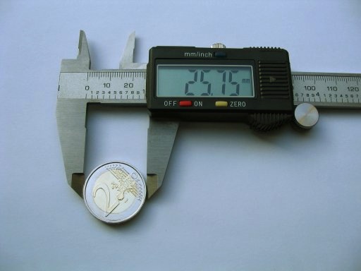
A refinement now popular is the replacement of the analog dial with an electronic digital display on which the reading is displayed as a single value. Some digital calipers can be switched between centimeters or millimeters, and inches. All provide for zeroing the display at any point along the slide, allowing the same sort of differential measurements as with the dial caliper. Digital calipers may contain some sort of "reading hold" feature, allowing the reading of dimensions even in awkward locations where the display cannot be seen. Ordinary 6-in/150-mm digital calipers are made of stainless steel, have a rated accuracy of .001" (.02mm) and resolution of .0005" (.01mm).[7] The same technology is used to make longer 8-in and 12-in calipers; the accuracy for bigger measurements declines to .001" (.03mm) for 100-200mm and .0015" (.04mm) for 200-300mm. [8]
Many Chinese-made digital calipers are inexpensive and perform reasonably well. One point worth noting is battery current when they are turned off. Many calipers do not stop drawing power when the switch is in the off position; they shut down the display but continue drawing nearly as muchcurrent. The current may be as much as 20 microamperes,[9] which is much higher than many established brands. Sometimes calipers may not work properly when the battery voltage has dropped relatively little; silver cells, preferably selected from a datasheet to have a constant voltage for most of their life, may give a much longer usable life than alkaline button cells (e.g., SR44 instead of LR44).[9][10]
Increasingly, digital calipers offer a serial data output to allow them to be interfaced with a dedicated recorder or a personal computer. The digital interface significantly decreases the time to make and record a series of measurements, and it also improves the reliability of the records. A suitable device to convert the serial data output to common computer interfaces such as RS-232Universal Serial Bus, or wireless can be built or purchased. With such a converter, measurements can be directly entered into a spreadsheet, a Statistical Process Controlprogram, or similar software.
The serial digital output varies among manufacturers. Common options are
  • Mitutoyo's Digimatic interface. This is the dominant name brand interface. Format is 52-bits arranged as 13 nibbles.[11][12][13][14]
  • Sylvac interface. This is the common protocol for inexpensive, non-name brand, calipers. Format is 24 bit 90 kHz synchronous.[15][16]
  • Starrett[17]
  • Brown & Sharpe[17]
  • Federal
  • Mahr (appears to offer Digimatic, RS232, and USB)
  • Tesa[17]
  • Aldi. Format is 7 BCD digits.[16]
Like dial calipers, the slide of a digital caliper can usually be locked using a lever or thumb-screw.
Digital calipers contain a capacitive linear encoder. A pattern of bars is etched directly on the printed circuit board in the slider. Under the scale of the caliper another printed circuit board also contains an etched pattern of lines. The combination of these printed circuit boards forms two variable capacitors. The two capacitances are out of phase. As the slider moves the capacitance changes in a linear fashion and in a repeating pattern. The circuitry built into the slider counts the bars as the slider moves and does a linear interpolation based on the magnitudes of the capacitors to find the precise position of the slider.